News
NEW EQUIPMENT INSTALLED Zeiss gom 3D Measuring Technology
Technical oriented is always our developing direction. This year, for Q.C. department we installed one new High Precision 3D measuring system in pursuit of better efficiency. It is ATOS Capsule 3D measuring machine from Zeiss Gom. Please see below more details.
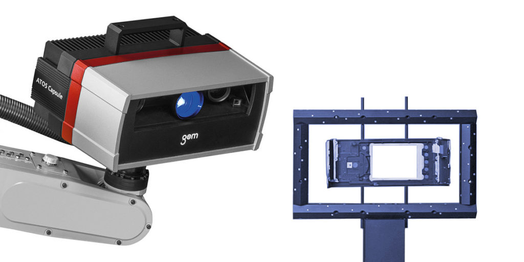
ATOS Capsule 3D measuring Technology
Due to its housing design, the ATOS Capsule provides process stability for automated applications. Made of plastic injection molding, the precisely manufactured unibody housing ensures maximum stiffness and precise measuring results for industrial use. Optics and electronics are protected against dust and splashing water.
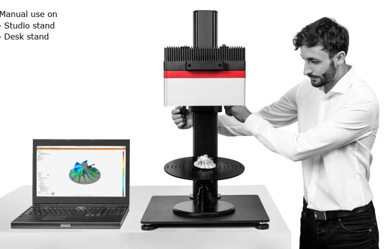
Optical 3D coordinate measuring machines are replacing tactile measuring systems and gages in many areas of industry. They capture more detailed and more easily interpretable quality information of an object with significantly shorter measuring times.
Whereas mechanical measuring systems capture data in a point-based or linear manner, optical measuring systems return full-field data about deviations between the actual 3D coordinates and the CAD data. As this measuring data contains all the object information, in addition to the surface deviations from the CAD, the software also automatically derives detailed information such as GD&T, trimming or hole positions.
The accuracy of optical measuring machines is not due to expensive and high-maintenance precision mechanics, but is rather based on state-of-the-art optoelectronics, precise image processing and mathematic algorithms. Few precision standards and automated calibration that can be performed by the customer ensure the accuracy of the machine. This also means no loss of accuracy due to wear under harsh conditions. As with tactile machines, measuring uncertainty is certified with the help of ball bars or step gauges.
Over 14,000 GOM measuring systems worldwide ensure the dimensional quality of automotive, sheet-metal, cast and injection molded products as well as turbine blades and wheels. In most cases, the detailed analyses are not used for a simple “OK”/ “not OK” evaluation, but rather form the basis for the optimization of production and machine parameters as part of a value-added measuring procedure.
- Highest precision (0.003mm)
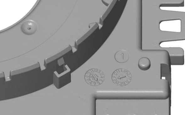
- Smallest features
- Encapsulated optics
- Protected electronics
- Dustproof / splashproof
- Automation for small parts
To ensure precise measuring accuracy, the GOM software packages have been tested and certified by the two institutes PTB and NIST. The accuracy of the inspection software is confirmed by the comparison of the results obtained with the reference results. The GOM software has been placed in Category 1, the category with the smallest measurement deviations.
Actual-nominal comparison – The calculated polygon mesh describes free-form surfaces and standard geometries. These can be compared with the drawing or directly with the CAD data set with the help of a surface comparison. A 3D analysis of surfaces as well as a 2D analysis of sections or points can be implemented in the software. CAD-based generation of standard geometries such as lines, planes, circles or cylinders is also possible.
Alignment – The GOM 3D software contains all standard alignment functions. These include RPS alignment, hierar-chical alignment based on geometric elements, alignment in a local coordinate system,using reference points as well as various best-fit methods such as global best-fit and local best-fit. Customers can also use their own specific alignments, e. g. for turbine blades, such as balanced beam or equalized nested.
Surface defect map – The function detects small defects and visualizes e. g. dents or sink marks. To visualize and quantify local bulges and depressions, the surface defect map directly works on meshes. By comparing the nominal and actual surface inspection, the new feature allows the compensation of global curvatures.
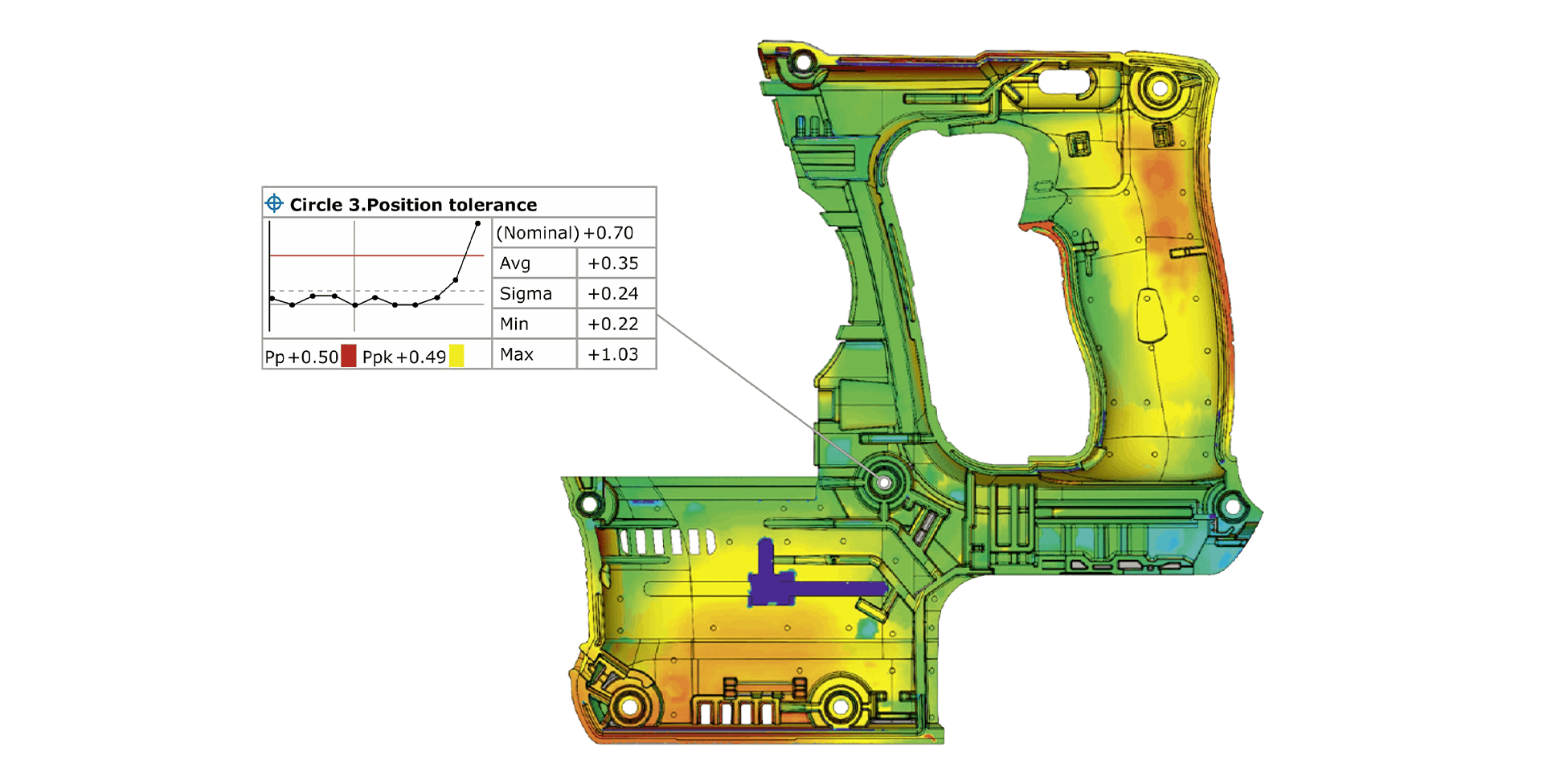
Trend, SPC and deformation analysis – The parameter-based approach of the GOM software enables trend analysis for multiple evaluation, e. g. for statistical process control (SPC) or deformation analysis. As a result, several parts or stages within a single project can be evaluated in a full-field manner, and statistical analysis values such as Cp, Cpk, Pp, Ppk, Min, Max, Avg and Sigma can be determined.
GD&T analysis – In contrast to the pure dimension analysis, the GD&T analysis focuses on the functional aspect of the part. Corresponding GD&T elements are, for example, planarity, parallelism or cylindricity. Both, a standardized analysis of 2-point distances and of the maximum mate-rial requirement as well as the position tolerance in local datum and coordinate systems are possible.
Airfoil inspection – Special functions are available for the quality control of turbine blades, which can be used, for example, to inspect the profile mean line, profile chord line or profile thickness of turbine blades on the basis of 2D sections. The profile centroid, profile radi and profile twists can also be calculated.
Reporting – The reporting module enables users to create reports containing snapshots, images, tables, diagrams, texts and graphics. The results can be visualized and edited in the user interface as well as exported as a PDF file. Templates are reusable, and each scene saved in a report can be restored in the 3D window.